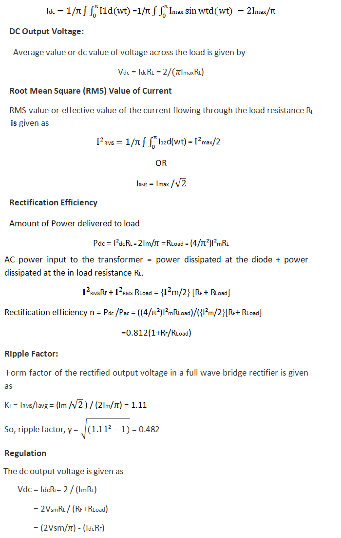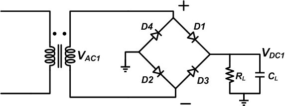

They provide control and battery backup from 1Mbit to 16Mbit external low power SRAM with up to 10 years of data retention, depending on the Supervisor, battery and SRAM type selected. For making 100 amperes, 50 volts full wave rectifier, how do I calculate the circuit capacitance to avoid the ripple voltage I mean which size of capacitor. TIMEKEEPER Supervisors convert standard low-power SRAM devices into non-volatile memory. Advanced TIMEKEEPERs include additional features such as programmable alarms, watchdog timers, system reset outputs and battery low warning flags STMicroelectronics TIMEKEEPER products add a quartz crystal, very low power oscillator and a clock/calendar circuit to provide real-time data. The efficiency, ripple factor, average value, RMS value all are same except the transformer utilisation factor(TUF). Bridge rectifier A diode bridge is an arrangement of four diodes in a bridge circuit configuration that provides the same polarity of output for either. From a center tap rectifier, the bridge rectifier has a difference only in the circuit arrangement. The advantage is long term data retention with fast READ/WRITE times and unlimited READ/WRITE cycles of standard SRAMs. The bridge rectifier consists of 4 diodes in a bridge circuit configuration. If this falls below a specific threshold it automatically write-protects the SRAM and switches the standby power supply to the internal lithium battery.

Accordingly the maximum voltage output that can be achieved is a minimum of 1.2 volts down on the peak voltage of the AC input. The power-fail circuit monitors the external power supply voltage. Does a full bridge rectifier increase voltage As most bridge rectifiers use silicon diodes, this drop will be a minimum of 1.2 volts and will increase as the current increases. We can define bridge rectifiers as a type of full-wave rectifier that uses four or more diodes in a bridge circuit configuration to efficiently convert alternating (AC) current to a direct (DC) current. STMicroelectronics ZEROPOWER products integrate low power SRAMs with a power-fail control circuit and a long-life lithium battery. What is bridge rectifier and its working Among the rectifiers, the bridge rectifier is the most efficient rectifier circuit. The formula tells you the maximum dc voltage you can achieve from a given rms.
#What does a bridge rectifier calculator serial#
Serial Real-Time Clock Product Selector A full-wave bridge rectifier is a specialized arrangement of diodes that.The simplest kind of rectifier circuit is the half-wave rectifier. Our devices are available in two industry standard serial interfaces: I☬ (Inter-Integrated Circuit) and SPI (Serial Peripheral Interface). As we have seen, this is exactly what a semiconductor diode does. Construction Of Full Wave Rectifier Four diodes are used in the bridge rectifier. This circuit gives full-wave rectification and is cost-effective as well, thus used in many applications. Instead of the standard asynchronous parallel SRAM interface, Serial RTCs use a serial bus. The full-wave bridge rectifier is a circuit consisting of four diodes arranged in a bridge-type structured figure as shown. Note that this bridge rectifier value is approximately half the PIV we determined for the full-wave rectifier design Thus, the source voltage (and the output DC component) of a bridge rectifier can be twice that of the full-wave rectifier designthis is why the bridge rectifier is a very useful rectifier design t A v S(t) v D(t) v 0.7 +A.

The following graph shows the input output signal of a bridge rectifier. Applying greater voltage than the peak inverse voltage will damage the diode and effect other circuit elements if associated. I have a 220V/400V/415V/440V AC to 24V AC transformer, and i have power bridge rectifier. Like ST's TIMEKEEPER® NVRAMs, Serial RTCs keep track of day-date-time, even in the absence of power. Peak inverse voltage of a bridge rectifier is calculated as PIV > V m.


 0 kommentar(er)
